GPS-Denied UAV Navigation
UAVs@Berkeley
Sponsored by:
Background
As one of the largest clubs at UC Berkeley with a goal of exploring the world of uncrewed aerial vehicles, we felt uniquely equipped to tackle the challenge of GPS-denied navigation presented by Theseus in the EECS106A course. Building atop of our existing drone platform from the 2023-2024 AUVSI SUAS competition season, we were able to add significant autonomous capability with new hardware and software while applying concepts and techniques from class.
Typically, drones rely on GPS to perform tasks like waypoint navigation and geolocation. There are certain times and places where this is impossible, such as indoor areas and places where GPS signals are weak or jammed. We decided to focus on the outdoor issue. Some challenges we needed to address include:
When sponsored by Theseus, having the task of gps-denied navigation was an interesting challenge. With our preexisting drone platform, we are able add more capability to our drone and with the help of Theseus, we were able to achieve some success.
This is an interesting project because of the challenges in gps-denied navigation. Usually gps is used to be able to get an accurate ground truth position and reduce errors that occur when trying to only use onbaord sensors, which is why gps is so popular for drone navigation. However, there are places where gps will not be able to reach the drone, such as caves, indoor areas, or areas of intense jamming. Thus, gps-denied navigation is a relevant topic in modern drones. Some challenges we need to address include:
- Reducing incremental errors from data collected from onboard sensors
- From last point on GPS, have the ability to travel along a path with minimal deviation from the planned path and accurately tell its location in terms of gps coordinates.
- Accurately estimate wind speeds to avoid drift
- Stream video data and SSH over WIFI
Design Approach
Components
- Cube Orange flight controller
- 6x MN8014 UAV Motors
- 2x 6s 30Ah Li-Ion batteries
- Six 29 inch diameter propellers
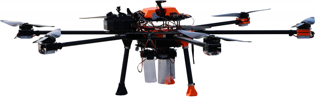
Our Drone "Sabertooth"
Characteristics
- Weighs 22.5 kg without payload
- 45 min flight time
- 49 kg maximum payload capacity
Design Objectives
- Add a computer and gimbal able to handle high quality camera data and compute its location through visual and velocity data
- Integrate wifi capabilities
- Add velocity and wind sensors to calculate wind drift
Design Chosen
We have chosen to enhance our existing drone platform by integrating GPS-denied navigation capabilities. This involved adding a dedicated computer and a gimbal onboard the drone, allowing it to navigate effectively using visual and velocity data without relying on GPS. The design builds on our existing platform, requiring minimal additional components while addressing the specific need for autonomous navigation in GPS-denied environments.
One of the key design choices was selecting the onboard computer. We considered two options: the Jetson Orin Nano and the Jetson Nano. The Jetson Orin Nano offers superior computational power, making it ideal for processing intensive visual algorithms. However, it is more expensive and has higher power requirements. In contrast, the Jetson Nano is more cost-effective and power-efficient but has reduced computational capability. The decision required balancing performance requirements with budget and power constraints, ultimately shaping the choice based on the specific demands of our application.
For the navigation method, we explored Optical Flow and Visual-Inertial Odometry (VIO). Optical Flow, which estimates velocity by tracking feature motion across images, is lightweight but less reliable in environments with sparse or repetitive textures. VIO, which combines visual data with inertial measurements, offers greater accuracy and robustness in a wider range of environments. Given the reliability required for GPS-denied navigation, Optical Flow was chosen as the primary navigation method, supported by reference materials and established documentation.
In the development process, a significant tradeoff involved choosing between the ORB (Oriented FAST and Rotated BRIEF) and SIFT (Scale-Invariant Feature Transform) algorithms for computing the transform between locations. ORB is significantly faster and less computationally intensive, making it suitable for real-time applications. However, it detects fewer features compared to SIFT. While SIFT provides higher robustness by detecting more features, it requires three times more processing time per image, making it less practical for real-time use on a drone. We selected ORB because its speed and efficiency align with the operational needs of the drone, and its feature detection accuracy, combined with the use of a FLANN-based KNN matcher, is sufficient for reliable navigation.
The design choices had a direct impact on how well the project meets criteria like robustness, durability, and efficiency in real-world applications. By integrating a gimbal, the system improved data capture stability, contributing to durability under various conditions. Efficiency was achieved by combining lightweight algorithms with hardware capable of meeting computational demands while minimizing energy consumption. Although higher-performance components such as the Jetson Orin Nano could have further enhanced performance, the cost and power tradeoffs made the Jetson Nano a more practical choice for this project.
Hardware Changes
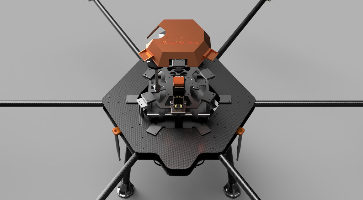
Our solution was built using a combination of existing resources and new components. We used our preexisting drone platform and a 3D printer to create custom parts that allowed us to securely attach the new hardware to the drone. This approach ensured the new components worked smoothly with the existing setup.
The system operates step by step to enable navigation without GPS. The drone itself had already been built and tested, so we focused on adding and integrating the new navigation system. This integration was key to maintaining the drone’s performance.
The process starts when the flight controller sends a signal to turn on the gimbal. The gimbal then captures images during flight and sends the image data to the Jetson Orin Nano computer using an Ethernet cable. Since the computer cannot handle all the images at full speed, it keeps only the most recent ones and ignores the rest. This helps the system run efficiently.
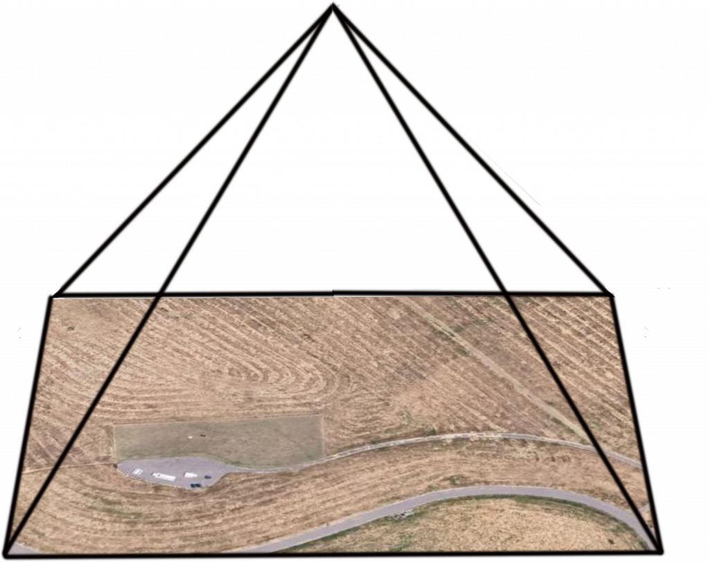
The computer then processes the images and compares them with reference images from Google Earth. These reference images come with labeled GPS coordinates that tell us the location of the image’s center. By matching the drone’s live images to these reference images, the system calculates the drone’s position and predicts its GPS coordinates.
Once the system determines the GPS coordinates, it sends this information to the flight controller. The flight controller updates the ground station with this data. At the ground station, we compare the predicted distances traveled by the drone to the actual distances recorded during the flight to check the system’s accuracy.
This step-by-step system allows the drone to navigate without relying on GPS. By combining existing technology with new components, we created a reliable and efficient solution for the task.
Nvidia Jetson Orin Nano Development Kit
This is the computer which is able to handle the images from the gimbal and have enough compute for many relevant computer vision algorithms
- 8 GB Ram
- 1024-core GPU

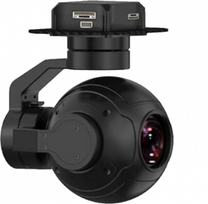
Siyi ZR10 Optical Pod
This is a high quality gimbal that we were able to afford given the budget. Compatible with Ardupilot and PX4 and able to do RTSP video stream, we are able to easily get the data off the camera and use for the computer to process.
- 10x optical zoom, 30x Hybrid
- 79.5 degree FOV
- 320 degree Yaw Axis Rotation
- Compatible with Ardupilot and PX4 (Mavlink)
- RTSP video stream


Hardware WiFi Stream
The final major hardware setup for this project was the creation of a reliable 2.4GHz Wi-Fi connection for access to the Ethernet video stream of the SIYI ZR10 and the SSH terminal of the NVIDIA Jetson Orin Nano from over 200m away. This stream is configured via a ground station sector antenna and access point (Mikrotik RB911G-2HPnD-12S) and a Wi-Fi access point onboard (Mikrotik Groove52). The Groove52 is configured as a Wifi bridge to directly connect the Ground Station Access point with the Orin Nano. The Ground Station Access Point is configured so multiple devices, laptops and phones, can connect and view the SSH terminal and camera stream of the drone. During testing, we achieved a stable connection up to 150m away with constant video and SSH terminal feed for script debugging and printed output.
Software

OpenCV
Open-source library for computer vision and image processing

Dronekit-Python
Python library for developing drone applications with Ardupilot integration

Ardupilot
Open-source firmware for autonomous vehicle control and navigation
Software Overview
Main Algorithm (live_gps_test.py) Running on the NVIDIA Orin Nano
This script hosts the main loop for our code execution. It consists of three functionalities: camera stream setup, GPS transformation calculation, and feature mapping.
Camera Stream Setup
In the first third of our code, we define all major global variables, initialize local variables, and connect to the drone flight controller via a UART connection. Leveraging Dronekit_Python’s GPS coordinate class, we have a function that uses an Ardupilot formulat for calculating the distance between two GPS coordinates. The assumptions of these functions make them accurate at distances under 10km, which makes them perfect for our drone camera frame. Then, we load in the google maps reference image, still_image, and apply a grayscale filter to it. Then, we use OpenCV’s video reader to open the rtsp camera stream from the SIYI ZR10 over Ethernet. Once we open the camera stream, we then capture a photo every 20 loop iterations which leads to a frame rate of capturing 4 frames per second.
GPS Transformation Calculation
In the first part of our analysis of a single frame, our reads the altitude of our drone from the flight controller over our UART connection. We calculate and physical meter size per pixel in both the x and y directions of the photo based on the SIYI ZR10 fields of view and the updated altitude. We also calculate the gps coordinates of any features in the still image using a similar transformation of finding the physical size per pixel. Since the feature mapping is one to one, we calculate the GPS coordinate in the reference, still_image, and assume the equivalent feature has the same GPS coordinate, and apply the inverse of the camera GPS transformation to predict the cameras GPS coordinates.
Feature Mapping
Our script uses ORB (Oriented FAST and Rotated BRIEF) for detection to create identify unique features in both the live camera frame and the Google Maps reference image. Each feature requires descriptors to assist in matching between the two images. The BEBLID (Boosted Efficient Binary Local Image Descriptor) class is for key point descriptor generation – here’s an article on how it helps! Once we have identified features and assigned descriptors. The algorithm then uses a FLANN-based matcher to match features in both images with similar descriptors. Many of the initial matches are redundant, so using Lowe’s ratio test, with a ratio of 0.95, we can check if two matches per feature are significantly different in length. If they are not, one of the matches is eliminated. Once all the matches are filtered, we still averaged 100 matches per image. To group matches into general locations on the reference image, we then used K-means clustering algorithm to group matched feature into 6 groups on an image. We were confident that one of the three clusters with the most matches had to be the current features in view. To ensure we were not matching to features that were very far away, 100’s of meters from when the last image was taken, we added a test that the median coordinate of the desired cluster on the camera image had to be within camera view of the last predicted coordinates (aka we could not have moved more than one photo length in less than a second). This eliminated all extra clusters and takes an images that looks like the Geotest 1 video to an feature set like that of Geotest 4. Once we had a singular cluster of matched features, we then iterated over each match in the cluster, if it was within 5 meters of the median of the cluster, then it is a valid feature point, and we follow the inverse camera transformation described earlier to predict the GPS coordinates of the UAV from the GPS coordinate of that feature point. After iterating over all the valid reference, we averaged the predicted GPS coordinates to come to a final predicted coordinate. This final prediction is calculated against the drones actual GPS coordinate to find our error. Then, the last predicted coordinate is updated with the new coordinate and the feature matching process begins again.
Software Flowchart
Software flowchart in how our system is able to predict its GPS coordinates based off of only visual data.

Results
The project had amazing success. Through only visual aid and a lack exact calibration, we were able to refine our predicted geo-positioning to within 10m of true GPS(given that our true GPS RTK was calibrated to 2m of accuracy). The since we are able to compare accurately with Google Earth satellite images, this provides a large space for more improvements such as better ground truth photos or more sensors. Since we were not able to get the Optical Flow in time, we were unable to move into true GPS denied navigation, but once it is attached is able to further improve the accuracy and safely navigate without the wind dangerously drifting the drone off the navigation path.
Below are the results of the image matching in Cesar Chavez park where we flew.
Orb Test
This is a test on the ORB algorithm using both a still image and a screen recording from Google Earth to simulate footage from our drone. We verified that the basic concept behind our project worked well and that even with a relatively noisy background, appropriate features were being found and matched.
Live Footage Validation
The next step was to validate our software with footage from a real drone. The video on the right was taken with a different off-the-shelf videography drone, and imported to the Orin to simulate a real flight. The still image is identical to the one used earlier, but with an edge-preserving filter applied. Note that the video was taken at night with very low visibility!
This is from a separate dji drone with a reliable camera which was tested as a first real life video camera stream that would be compared to the google earth photo. Results were satisfactory especially for night flight.
Screen Recording
A screen recording from the ground station computer of the Mission Planner GUI and the data that is being sent back by the Jetson Orin Nano over SSH while the drone is flying. The data stream shows the comparison between the real and estimated GPS position, as well as the error in meters.
Geotest 1
Here is footage from our first flight test with our hexacopter. Every feature match, including matches that are not used in our calculations, are displayed. A higher number of features was calculated for the reference Google Earth photo to increase the likelihood of correct matches.
Geotest 2
2nd real flight
Geotest 3
3rd real flight. As we see, it is able to match key features and although there are false positives, we are able to filter them out.
Geotest 4
Flight Summary
Conclusion
Results and Evaluation
Our solution partially met the design criteria we established at the outset. Specifically, we successfully achieved the goals related to visual positioning and Wi-Fi communication. These core functionalities demonstrated that the system could effectively process images and manage data transmission as planned. However, due to budget constraints and time limitations, we were unable to incorporate the Optical Flow sensor into the system before the semester ended. As a result, the full navigation capabilities were not functional at this stage. Despite this, we remain confident that with additional time, we will be able to integrate Optical Flow and complete the navigation system.
Challenges Encountered
We faced significant difficulties during the project, most notably with the Jetson Orin Nano. On the planned flight test day, the device unexpectedly malfunctioned, requiring a complete reinstallation of the Jetson Orin Nano Linux OS.
Additionally, there were issues with the camera stream. The image pipeline was unreliable, with inconsistent data transmission that hindered real-time processing. This made it challenging to achieve smooth and accurate image analysis during testing.
Flaws, Hacks, and Potential Improvements
Our solution, while functional in parts, has some limitations and areas for improvement. One major shortcoming is the lack of Optical Flow integration, which would have enhanced accuracy and robustness. Furthermore, the current setup requires more calibration to optimize performance, particularly in terms of camera stability and data processing reliability.
If we had more time and resources, we would focus on addressing these issues. Improvements would include refining the camera pipeline to ensure a steady and efficient stream of images, calibrating all components to minimize errors, and fully integrating the Optical Flow sensor to achieve the intended navigation functionality. These enhancements would significantly improve the overall performance and reliability of the system.
Meet the team!

Matthew Song
Matthew is a senior in EECS who has been building and flying drones since he was 7. He has a strong interest in mechatronics, and does aerial videography for fun.
Major Contributions:
- Test Pilot
- Set up RTSP stream and initial components of video pipeline
John Lomax
John is a senior in EECS who is interested in UAV hardware design and autonomy software. He has experience with PCB design, Ardupilot, ROS, MAVROS, and UAV autonomy software stack development.
Major Contributions:
- Creation of Computer Vision loop for K-means
- Feature-mapping, and GPS prediction algorithm
- Setup of onboard wifi stream for video and SSH terminal data
- Ground station operator for test flights

Kyle Hornsby
Kyle is a senior in ME who is interested in mechatronics , Drone development and design, and machine learning. Has experience in CAD development, ANSYS simulation, MatLab, Python and C++ development.
Major Contributions:
- Hardware adjustments
- Flight testing, debugging.

James Lukas
James is a senior in EECS who is interested in robotics and sensor applications. He is doing research in UCSF on medical robotic applications and computer vision.
Major Contributions:
- Jetson Orin Nano setup,
- Driver Installation
- Flight test setup

Jimmy Nyi
Jimmy is a senior EECS major interested in developing new UAV technologies. He has experience in KiCAD, PCB design, Python and ROS.
Major Contributions:
- Website development
- Debugging flight test
- Flight test equipment maintenance
What's next?
To take this project to the next level, we will be integrating an optical flow sensor to enable full GPS-denied autonomous flight. The optical flow sensor allows us to measure our position and movement significantly more accurately than IMU-based methods, and is required by Ardupilot to fly with the GPS disabled.